v1.41a - G-Code Export Dialog, Per-Tool Measure Units, DXF Import, UI Improvements, and more!
v1.41a is here! Users should be able to receive it via automatic updates for both the paid and trial versions of PixelCNC - with the free trial including automatic update functionality as of v1.39a, so users running an older version will still need to manually download the update.
This update has a pretty typical number of additions, changes, and fixes for an update, as have the last half-dozen updates. While I prefer to put out updates more often they tend to be smaller and where PixelCNC is at now I feel a 2-3 month interval is better suited as we approach beta. This version was a bit of a gruel with some of the bugfixes that needed chasing down and it's a relief to have all that all situated now. Here's the changes.txt for v1.41a:
- added G-code export dialog with options for controlling how a project's operations are output into one or more CNC program files
- added per-tool units-of-measure allowing tools with inch-dimensions to be used in metric projects and vice-versa
- added DXF import support for creating paths-layers from DXF vectors
- added new algorithm for converting polylines to paths which improves quality of trace-to-paths and DXF polyline import
- added new post-processor values for disabling the inclusion of commands which are not used by many CNCs/controllers (post version upgraded to 1.1, update any custom posts to include the new parameters)
- added toolpath-calculation resolution setting to CNC/CAM Settings dialog
- added new stipple density algorithm to replace the slower and more cumbersome "advection" algorithm (will require tuning parameters for existing projects that have stipple operations to produce similar/equivalent results)
- added experimental support for relative coordinates in G-code (untested on CNC!)
- added maximum radius parameter to spiral milling operation limiting cut extent
- added and changed some UI value inputs from knobs/sliders to editboxes
- added units-of-measure indication to relevant value inputs and readouts
- added ability to join paths while in path-editing mode
- added ability to press TAB or SHIFT+TAB to navigate between UI edit boxes
- added ability to select section of string in editbox and delete/overwrite
- added layer angle +/- 22.5 increment and reset-rotation buttons
- added canvas resolution increment/decrement buttons
- added small-buttons toggle in UI settings for view buttons bar
- added drawing of selected colors on settings dialogs
- added registry enumeration of user-installed fonts which cannot be enumerated using the same mechanism that enumerates system fonts
- added glossiness adjustment to view settings dialog
- added warnings for some operation parameters to prevent users from accidentally using invalid values that a toolpath cannot actually be generated with
- changed stipple operation's bias/contrast parameters to min/max diameter
- changed trace-to-paths function's resolution to dramatically improve quality
- changed view rendering when moving active layer to hide other layers' bounds
- changed canvas layers list to show visible/delete buttons on layers at all times regardless of whether or not they're currently selected
- changed simulation playback to be able to update tool position by fractions of a tool move, for more granular speed control and fluid motion
- changed metric value readouts from two decimal places to one decimal place
- changed default UI font from Tahoma to Fixedsys
- changed path node deletion to behave in an opposite fashion regarding the holding of the SHIFT key, deleting a node no longer splits a path unless SHIFT is held down
- changed view-camera input behavior to not move around as readily when trying to select paths, nodes, or layer handles
- changed some of the math involved in polyline decimation used on toolpaths and other contouring functions to improve detail preservation
- changed maximum simulation area from 2048px to 3200px
- fixed profiling operation minimum-depth having no effect on generated toolpath
- fixed pocketing operation minimum-depth having no effect on generated toolpath except corrupting it if used with ramp/helical entry cut modes
- fixed loading of older projects w/ pocket operations, updating contouring offset using wrong tool's radius to update to v1.40a's change in contour offset
- fixed selection rectangle in path-editing mode getting 'stuck' if dragged into the user interface overlay
- fixed layer z-origin editbox not allowing negative values
- fixed editbox appearing to lose keyboard focus if mouse is moved into 3d view
- fixed edge-shading on slice-stack rendering of canvas and simulation
- fixed delayed start/close under Windows 10 caused by logging mechanism bogging down when logging detected TTF/OTF fonts and supported OpenGL extensions
- fixed UI fonts' overwrite caret when user has pressed the INSERT key
- fixed crash when un-doing creation of new path in path editing mode
- fixed edge-shading of simulation with slice-stack rendermode (non-raymarched)
- fixed crash when rectangle-selecting paths in path-editing mode
- fixed bug preventing paths from being added to profiles for a pathsweep
- fixed miscellanious issues caused when defaulting user configuration while working with a metric project
- fixed selection rectangle drawing/precision issues in path-editing mode
- fixed CTRL+A select-all not working when editing text layer if cursor is already at the end of the text string
- fixed improper UI tooltip coloration
- fixed multiple issues with various raster-layer parameters being ignored when merging down with another raster-layer
- fixed issues when dragging a layer's width/height to zero
- fixed simulation mesh not updating with canvas size/position changes
- fixed layer property changes in UI not showing original layer in view before applying new property changes
- fixed positioning of tooltips so as to not be obscured by mouse cursor
- fixed bug causing stray cuts when horizontal/pocketing operations using rest-machining and a ramping entry cut fail to retract to safe-z
- fixed bug in simulation playback causing tool to "stick" while operation simulation progress continues incrementing
- fixed crash when canvas quality is set to zero in the View Settings dialog
G-Code Export Dialog
Thus far, PixelCNC only allowed breaking up a project's exported G-code into separate CNC programs through the use of the "include operation" toggle on each operation, which appears as a chain-link icon on the selected operation when in the Project Operations mode. The operation include toggle still exists, and still has an effect on the CNC simulation, rest-machining, and exported G-code. However, users now have the ability to export G-code using several different modes which may eliminate the need for the use of the include toggle in many situations. Previously, users working with a CNC not equipped with automatic tool-changing capabilities would need to manually export their project's operations by toggling off the include-operation on operations they did not want included in their exported G-code file, or if they just wanted to export individual operations each to their own CNC program file they'd have to toggle off including all other operations and perform a G-code export by-hand for each operation.
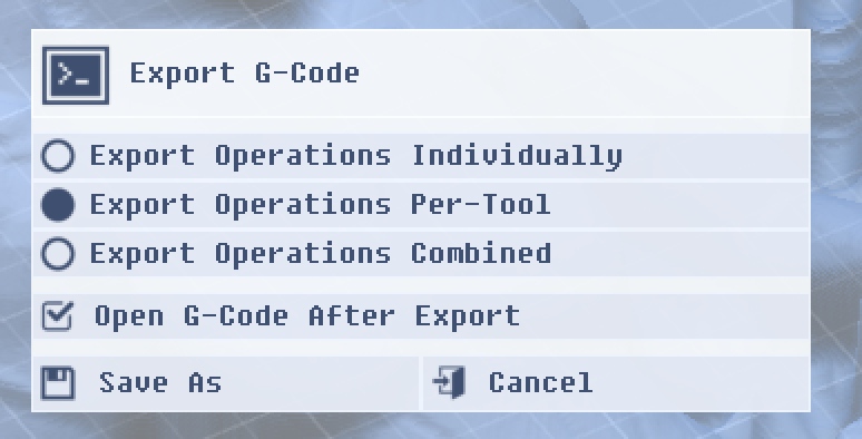
A project which uses a quarter-inch end mill to perform roughing and re-roughing operations that then comes in with an eighth-inch ball nose for pre-finishing and finishing would require that the user disable the include-operation for the finishing operations to export the roughing operations as one file, and vice-versa to export the finishing operations which use the ball nose end mill. This would allow them to perform all their initial quarter-inch end mill roughing in one go and then switch tools manually before performing the finishing operations. With the new Export G-Code dialog users can simply select "Export Operations Per-Tool" to accomplish the same result, without needing to bother with the include-operation toggle.
Reworked Stipple Algorithm
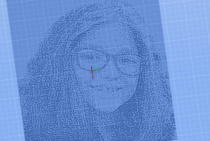
Yes, this is the 3rd incarnation of the Stipple operation's toolpath generation algorithm. It may be tweaked some in the coming weeks/months but the core will likely stay the same. It's a bit trickier to use than before - there's no longer a "step size" which sets the initial distance between stipples. In fact, there's no more regularly-spaced stipple functionality at all. Stipple placement and density is directly dictated by the canvas' height/depth. I'll probably at least add back in an option for fixed-spacing stipples that just vary in diameter to convey light/dark contrast, we'll see.
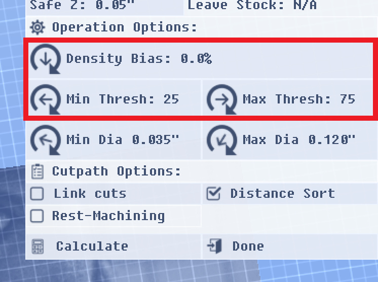
The new stipple operation's parameters can be a bit tricky to make sense of initially. It's a good idea is to start with the settings as seen above and tweak the min/max threshold values first. The min/max stipple diameter parameters are up to you and depend on the nature of the canvas you're trying to generate a good stipple distribution for. What range of stipple sizes do you want to have? Darker areas result in larger stipples and vice-versa. If after adjusting the min/max threshold values you are simply not getting enough stipples then go ahead and try increasing the "Density Bias" parameter to increase the overall density of stipples. For most images this should probably be kept at 0% and users likely will only need to adjust the Max Thresh value to manipulate the density of stipples. Lighter images will probably need their density bias nudged up some.
One thing that's bugging me about this new algorithm is that stipples can start to bunch together into lines, like a reaction-diffusion pattern. I'm working on breaking them up a bit more so that they form uniform distributions.
Loading 2D DXF Geometry as Paths-Layer(s)
PixelCNC now (finally) supports loading ASCII DXF files as new paths-layers. If a DXF contains multiple layers they will automatically be divided up into multiple canvas paths-layers, rather than all being lumped into a single paths-layer. Loading a DXF with a lot of geometry can take a little time due to some pre-processing that links up multiple separate geometric entities into continuous paths. A proper DXF file will have the last vertex of one entity match exactly the first vertex of another entity, with the same XY coordinate. PixelCNC utilizes a user-configurable threshold value for DXF files where the vertices do not perfectly match for entities that are intended to be linked together. This tolerance setting can be found on the "Geometry Settings" dialog in the Config menu (which has been renamed from "Model Settings" in this release).
I didn't want PixelCNC to join the "partial-DXF support" club to only have a tiny narrow subset of DXF files actually work properly but there were no DXF libraries that I could've used which were a good fit so I had to write a parser from scratch. While PixelCNC's DXF support is still not exactly 100% it should be able to handle a much wider range of DXF files thrown at it than the majority of 3rd party software out there not produced by AutoDesk. If anybody encounters a problematic DXF please send it on over so we can figure out what the situation is and resolve whatever underlying issues may be involved.
Spiral Operation Max-Radius
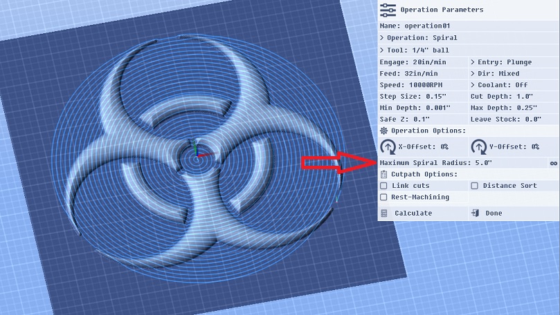
The spiral operation now includes a "maximum spiral radius" parameter, so that projects utilizing a spiral toolpath do not need to figure out how to deal with the spiral toolpath entering the corners of the project if they wish for a circular cut area.
Improved Polyline-to-Paths Algorithm
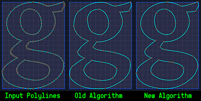
One of the internal algorithms which is used for creating a paths-layer by tracing the canvas or a layer at a specific Z height and now also to convert loaded DXF entity geometry into paths has been re-worked a bit to output paths which are better fitted to the original input polylines while also utilizing less nodes per generated path. As you can see above, the old algorithm doesn't capture the curvature of some parts of the original polyline shown on the left very well. The top of the outer polyline is a little lopsided and uneven as is the bottom-right section. On the right it's easy to see that the original curvature implied by the input polyline vertices is better captured and reproduced throughout.
The original issue with the old algorithm that motivated re-working it can also be seen in the image. In many situations there would result "remainder" vertices, where the algorithm would resort to just copying over some of the original input vertices and not attempt to fit a curve. This was due to the algorithm constantly splitting the polyline into two separate curves and attempting to generate a curve that fits them. If the curves did not fit well enough it would find the polyline vertex which deviates the most from the candidate curve and split the polyline there to recursively divide and conquer. After enough subdivisions the algorithm could very easily wind up with a sub-section of a polyline that didn't have enough vertices to attempt fitting a curve to, and so it would resort to simply outputting the raw vertices with no control points.
The new algorithm uses a different approach to curve-fitting to the input polylines and is able to do a much better job of winding up in a "last resort" situation, so there are less groups of vertices clumped together that could easily be approximated very well using a node or two and their control points to manipulate the path's shape to fit.
Units-of-Measure Readouts
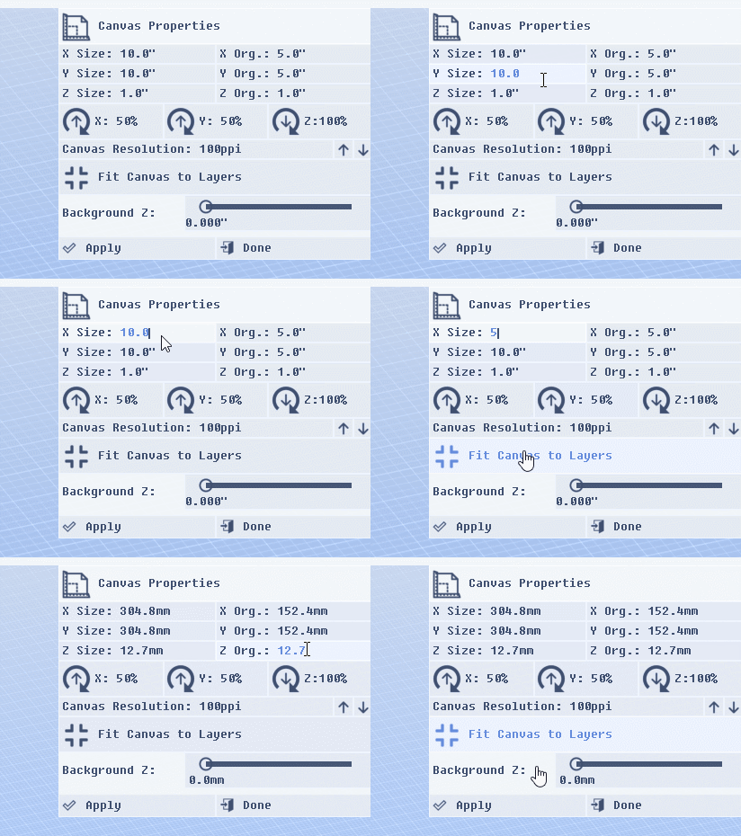
For all relevant value and parameter readouts and inputs users can now see what units of measure the value pertains to, which should make it much easier for users to maintain their bearings when entering values, especially now that there are...
...Per-Tool Measurement Units!
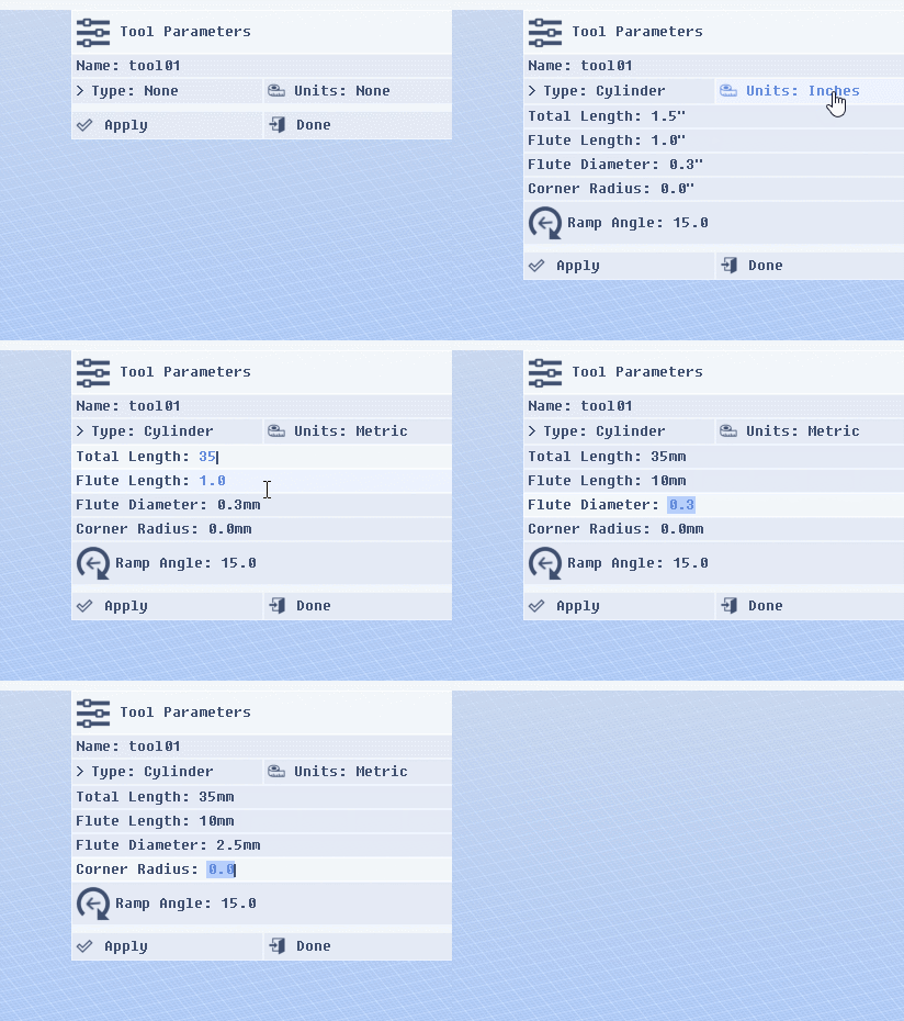
Previously, a PixelCNC project would be defined entirely in either inches or millimeters (metric), which was also the measure units that all tools had to be defined in for the project. Now users can use tools defined in either measure units regardless of the units that the project is defined in.
Improved Editbox Behavior
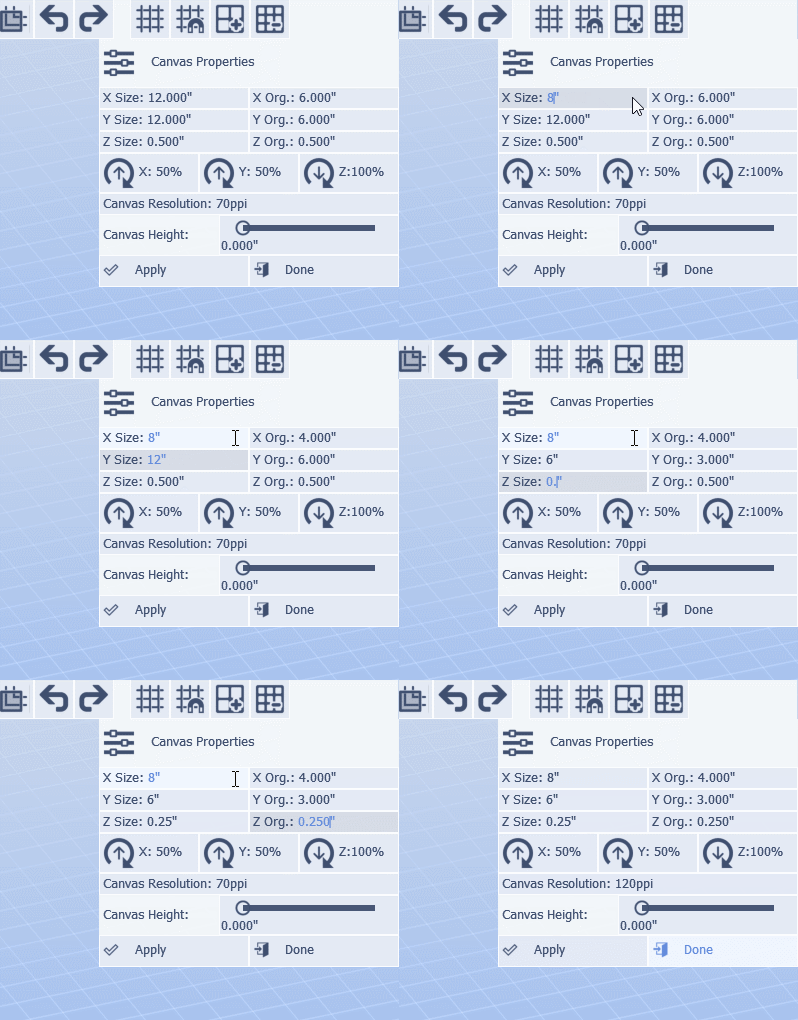
Editboxes in the user-interface have also been improved. Users can now select characters to overwrite them as well as use the TAB/SHIFT+TAB to move between editboxes via keyboard.
New Post-Processor v1.1 Parameters
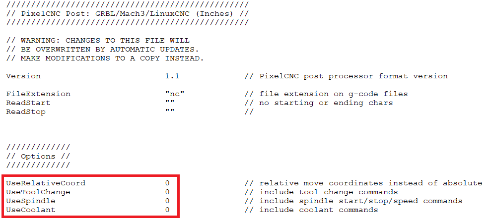
PixelCNC is capable of producing G-code for controlling the spindle, coolant system(s), and issuing tool-change commands per each operation's parameters. Not all machines support these commands and some simply ignore them when encountered, others will be tripped up by them and error out in the middle of running a program. Users can now simply disable the inclusion of any spindle/coolant/toolchange command blocks in generated G-code rather than having to make a custom post-processor that has blank block format templates for them.
These new commands have been added to PixelCNC's included post-processors to update them to the new v1.1 parameter set. These values will default to the equivalent of the v1.0 post-processor behavior for v1.0 post-processors. This is so that users with custom v1.0 posts for their machine can expect the same G-code to be generated as before. Users can either simply add the parameters to their own posts to update them to v1.1 (be sure to change the "Version" parameter to 1.1 or they'll be ignored) or continue using them as v1.0 posts, or customize the included posts to re-create their existing v1.0 posts. Remember to make a copy of the post(s) you want to use as a base and modify that so future updates won't overwrite your posts!
Enumerating User Fonts
Windows 10 by default installs fonts to the current user's folder, rather than the age-old "X:\Windows\Fonts\" folder, unless the user explicitly installs the font "for all users" from the right-click menu. This is an issue that has plagued users of many different programs which access and parse the font files directly, rather than through Windows API calls, (Inkscape, for example). PixelCNC will now seek out TTF/OTF font files among the current user's fonts folder in addition to the fonts installed to the OS' fonts folder. Please let us know if you still have an issue with PixelCNC not showing an installed font when editing a text-layer.
Fixes, Fixes, and More Fixes!
There were a lot of things to fix, and I just kept stumbling across them one-after-another while I was in the middle of working on something else. I'm sure there will be more that are stumbled over in the coming months, at least these ones are out of the way. Here's a bit more info about some of the more interesting fixes.
Slow Initialization on Windows 10: One of the big issues that I noticed on Windows 10 after finally switching my main work computer from Windows 7 to it was that writing out to the logfile was extremely slow. During PixelCNC initialization it logs the names of all the enumerated fonts and OpenGL rendering extensions, this means dumping hundreds of lines to the logfile. In Windows 7 this happens virtually instantaneously, but on 10 it takes its sweet time which makes PixelCNC appear to take a while to startup. After some hunting and digging and through deductive reasoning it was determined to be an issue specifically with writing to the logfile. This has been fixed and now Windows 10 users experiencing the slow startup should be experiencing the same fast startup that was a given on Windows 7.
Wrong Pocketing Contour Offset With Pre-v1.40a Projects: The pocketing operation received a change to the contour offset parameter where the tool radius was automatically applied so that the pocket would be the same size as where the canvas is contoured at. This required updating older projects' offsets so that their pockets would remain at their original size when loading them. A bug in the code was causing this functionality to always use the first tool index to calculate the delta for the offset parameter, no matter what tool index the operation actually used.
Selection Rectangle Issues: The selection rectangle for selecting paths/nodes while in paths-editing mode could get "stuck" if the mouse cursor left the 3D view while the rectangle was being dragged, into the UI. The result was a selection rectangle that just sat there, even after releasing the left mouse button and/or the SHIFT button. Another problem was the precision of the selection rectangle when calculating whether or not paths or nodes were inside or or intersecting the selection rectangle. If the camera was pointing straight down the selection calculation was fine, but the shallower the camera pitch angle the more inaccurate the calculations involved would become. The position of the nodes and paths was calculated to be at the wrong Z plane, unless the canvas machine origin was placed at the bottom of the canvas. Lastly, a seemingly-random crash would occur at times when selecting paths with the selection rectangle - which was trickier to figure out how to reproduce so that the root cause could be chased down.
Merging Down Raster-Layers: In simple cases merging one raster-layer with another seemed to work fine, but if more complexity were in play the resulting combined layer would not be the same as what should be expected. The Z position and size of the layer being merged down was calculated improperly and resulted in unpredictable results in different blending modes that didn't match up with how the layers composite to produce the canvas. Some parameters were completely ignored during a merge-down as well.
Dragging a Layer's Dimension to Zero: This was partially resolved in v1.40a where previously a layer's width or length would get stuck at zero if one of the handles were dragged and released, to where the handle couldn't be grabbed again to stretch the layer back out. While the solution worked great with layers that weren't rotated at a non-zero angle it would behave very strangely otherwise. Layers would jump around strangely if an edge were dragged to the opposite edge and released, unintentionally shifting the layer's position around in an inconvenient fashion.
Simulation Size/Position Changes: After creating an operation and simulating it if the canvas size and origin were changed the simulation system would become rather glitchy. The simulation geometry and rendering wouldn't update properly and sometimes not even be able to simulate an operation properly anymore until after its toolpath had been re-calculated (which is what users should do in the first place).
Tooltips Obscured by the Cursor: Toward the edges of the PixelCNC window it was difficult to read tooltips at times because they'd pop up right beneath the mouse cursor due to being offset away from the edges of the window where they wouldn't be readable at all.
....and more!
What's Next?
Moving forward, the plan is to start fleshing out the raster/path/text editing functionality. Advanced raster-editing functions akin to Photoshop filters, vector editing functions such as boolean merging operators and expand/contract/simplify/polygonize, as well as more advanced text-layer functionality including text-along-path, manipulating individual character orientations, and other useful features. Different brush-stroke modes like blur and smudge/drag are also in the works and raster-editing as a whole is set to receive further refinement in order to make it easier to use.
As stated in previous devlog posts there are also some new operations planned. There's a handful of new ones that are all relatively similar and I'd like to come up with a new one that's artistically inspiring and really sets PixelCNC apart from everything else out there. I'd also like to really flesh out the labyrinth to be able to do much more interesting maze patterns.
The project file format involves compressing depthmaps to the PNG image file format, which includes raster-layers and operation simulation depthmaps. This tends to cause project saving to be extremely slow and also doesn't really do that great of a job compressing the depthmaps. The PNG compression PixelCNC utilizes is designed for 24-bit RGB and 32-bit RGBA images whereas depthmaps in PixelCNC are just single-channel 32-bit floating-point value "images", or "scalar-fields", and it just doesn't make sense to utilize PNG to compress them even if it achieves ~50% compression by compressing depthmaps as 32-bit RGBA images because it compresses very slowly and just isn't the right fit for the task at hand. I'd like to employ a lossless compression solution that's faster and does a better job for single-channel 32-bit float depthmaps than what PNG does. This is something that will probably take a while but it would also benefit the project auto-backup functionality as long as saving a project file can be reduced to a few dozen milliseconds. Currently the auto-backup functionality is defaulted to being disabled because saving a project is very slow due to the PNG compressor.
I'd also like to add visualizations for the different operations, so users can see what to expect of an operation's toolpath before selecting an operation. This is probably something that will be done closer to beta though, along with the built-in help/tutorial stuff.
PixelCNC Has Moved: deftware.org
CAM software developed by artists for artists to create unique and original works on a 3-axis CNC router or mill.
More posts
- v1.53a - Hotfix: Trace To Paths Crash ErrorAug 19, 2021
- v1.52a - Canvas/Simulation Color Curves, Optimized Stroke Paths + Shapes From Pa...Aug 18, 2021
- v1.51a - Hotfixes: Offset Limiting Max Depth, Adding Path Sweep Profiles, etc.Aug 03, 2021
- Fixed Auto-Update Crash on Startup - 20% Off Sale!Jul 29, 2021
- v1.50a - Smooth/Smudge Brushes, Model-Layer Scaling, Remove Layer Bottom, Metric...Jul 29, 2021
- v1.49a - Duplicate Layer fixMay 11, 2021
- v1.48a - Miscellaneous fixesMay 10, 2021
- v1.46a - Faster more precise contouring, dithered stipple improvements, text-lay...May 04, 2021
- v1.45a - Misc bugfixes and improvementsFeb 16, 2021
- v1.44a - Paths Carving, Tessellated Carving, Raster Tiling, Raster Tilt Angles...Jan 15, 2021
Comments
Log in with itch.io to leave a comment.
Nice update. Thank you. I will test during the week-end.