v1.23a - Intel Gfx Fix, New Simulation Render, Op Coolant, Better Stipple, Bugfixes... What's Next?
Pushed v1.23a update via auto-update system. Please share your experience using the auto-update installer, which has been added into PixelCNC since v1.20a. The public releases have skipped over v1.22a due to the fact that it was used as an internal testing/debugging version for solving a problem a customer was having.
v1.23a Changes
- added parallax-mapped simulation system to improve performance/fidelity
- added visual depiction of cutter geometry when in simulation mode
- added option to "link cuts" for parallel operation when using 'mixed' cutting direction
- added coolant mode to operation parameters
- added preemptive detection of graphics adapters that are not multisampling-friendly
- added "always update" option for 3d view rendering
- added simulation cell coalescing to reduce overhead of updating individual cells
- added automatic reallocation throughout to reduce overall memory use
- added a z-offset to drawn toolpaths to reduce z-fighting with mesh geometry
- added green start and red end points rendered on toolpath
- added mutex to prevent race conditions when allocating memory
- changed pixels-per-inch enforcement to affect project mesh in 3d view
- changed user interface layout, rearranged operation parameters
- changed simulation resolution to be locked while simulation playback is active
- changed stipple advection repulsion to produce wider range of stipple densities
- changed max project pixel/inch to produce best resolution
- improved toolpath generation quality (may be a little slower than previous versions)
- increased size of toolpath g-code command parameters buffer from 4mb to 16mb
- increased maximum size of image-allocation pool to prevent img_alloc overflows
- increased reliability of horizontal toolpath by adding tolerance value
- fixed toolpath blending colors between feeds/rapids, now solidly delineated
- fixed horizontal toolpath generation bug: duplicate end vert added with same origin
- fixed horizontal toolpath adding second-to-last vertex too close to last vertex
- fixed parallel toolpath adding stray ending cut to origin at angles >= 270deg
- fixed stale user interface state when loading a project
- fixed tool-change g-code command having tool index before command
- fixed g-code stopping/starting spindle/coolant for toolchange when next op uses same tool
- fixed problem loading projects with a different units of measure from the configured one
- fixed crash when generating inches medial-axis toolpath after generating one for metric project
- fixed cnc toolpath simplify value not scaling with project units of measure
- fixed worker threads unable to process images quickly when 'cap framerate' is disabled
- fixed power-of-two simulation resolutions causing artifacts in simulated cuts
- fixed toolpath remaining visible after removing operation when setting type to 'none'
- fixed miscellaneous memory leak caused by early termination of toolpath generation
- fixed "program has stopped working" when window is minimized on certain system configurations
- fixed simulation perpetually updating when selecting another operation when actively simulating
- fixed "simulated cut generating..." getting stuck on statusbar after simulated cut is completed
Simulation System
The simulation system has been partially revamped. No longer does it generate a subdivision mesh the way the project mesh or CAM toolpath generating algorithms do. This is because the simulation needs only to be a 3D visual representation of a dynamically generating depthmap. To resolve the general jankiness of the original simulation system's generated mesh geometry the subdivision mesh system was replaced with a 'parallax occlusion mapping' setup which employs a pixel shader for performing raymarching along the simulation depthmap, and a static low-resolution grid mesh of triangles which is offset by a low-resolution depthmap to serve as the 'proxy geometry' from which raymarching begins for each screen pixel.
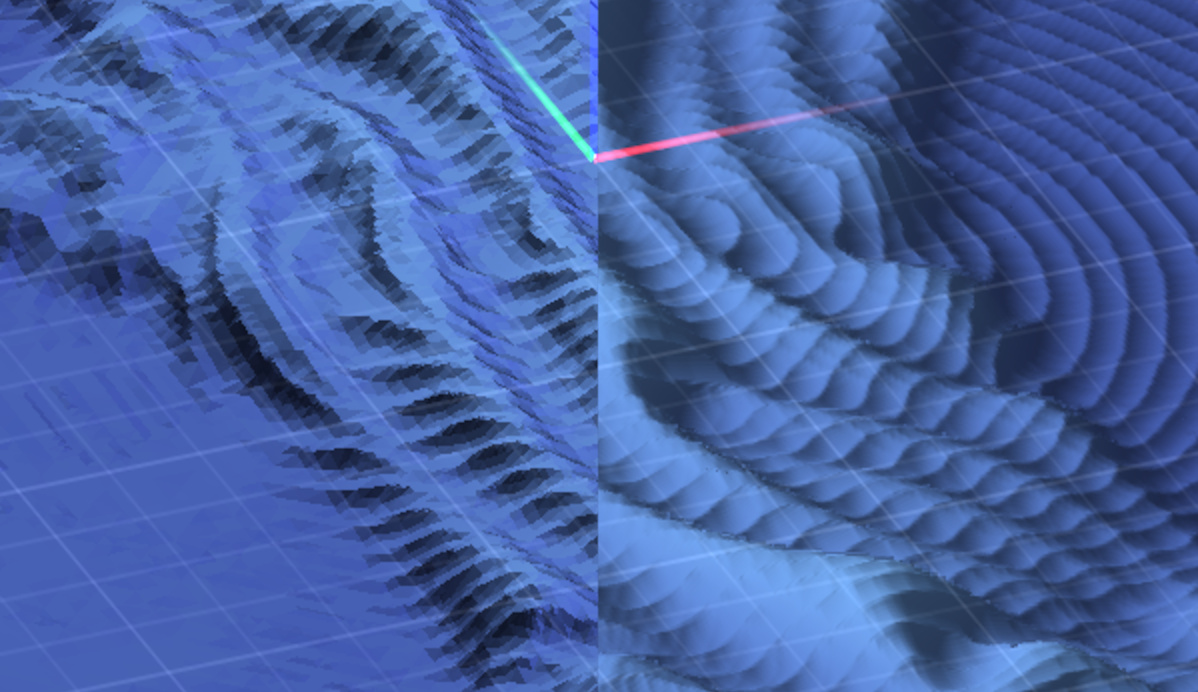
As you can see above the old simulation (left side) relied on drawing generated triangles via a subdivision algorithm which divides large triangles into smaller ones where there's detail in the depthmap. The new method of rendering directly renders the simulation depthmap (right side), requiring that only the depthmap itself be updated to the GPU, which is much faster. Previously, both mesh geometry and a texture had to be generated on the CPU and then uploaded to the GPU for drawing with. Between the CPU work and uploading of both geometry and texture data, the old simulation update system was much slower than the new system.
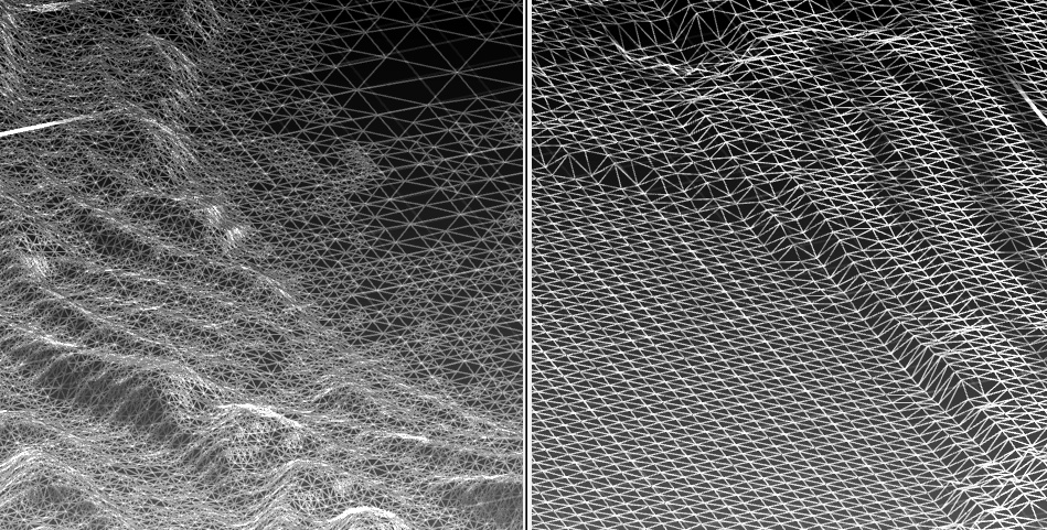
The image above contrasts the geometry actually being rasterized by the GPU with the old and new simulation systems. There is a profound difference in the number of triangles being drawn by the old simulation system (left), which had to be generated wherever cuts were being simulated, and then uploaded as individual sections, or 'chunks', to the GPU, and the mesh being drawn by the new simulation system (right).
The new simulation system renders a 100% static mesh that just sits in GPU memory, unchanged. The vertices of the mesh are displaced vertically on-the-fly by a low-resolution version of the simulation depthmap inside a vertex shader on the GPU. This low-resolution depthmap is produced using a special algorithm which outputs highest pixel of all of the pixels of the original depthmap that map to each destination pixel in the mesh-displacement depthmap. This ensures that each vertex of the resulting mesh is never below the simulation's depthmap.
This mesh serves as the 'proxy geometry' with which the full resolution depthmap is raymarched in the direction the camera is facing. Each ray basically originates at the surface of the proxy geometry, and traced into the simulation depthmap. The simulation could very well be rendered using one single flat polygon, and skip all the downscaling and proxy geometry steps, but the end result would be that each pixel generated by the GPU must perform a larger number of marching steps, as the distance between a polygon situated at the top surface of the project and the depths of the depthmap would be larger. The proxy geometry serves to reduce the total number of raymarch steps that are needed to find each pixel's ray-depthmap intersection point by loosely conforming to the depthmap itself. At the end of the day the triangle rendering capabilities of the GPU are being leveraged to minimize the total number of fragment shader operations needed to render the simulation.
The end result is dead-sexy:
Tool Geometry
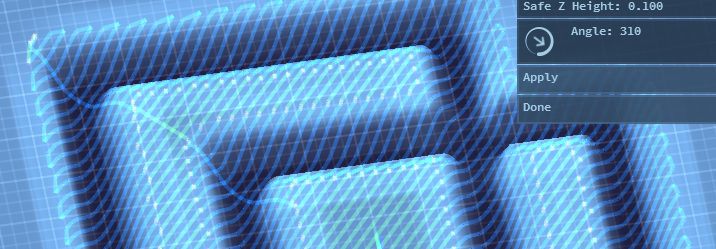
The simulation system also now draws the simulated operation's cutting tool. The cutter is positioned at the end of each simulated cut that is generated with each update.
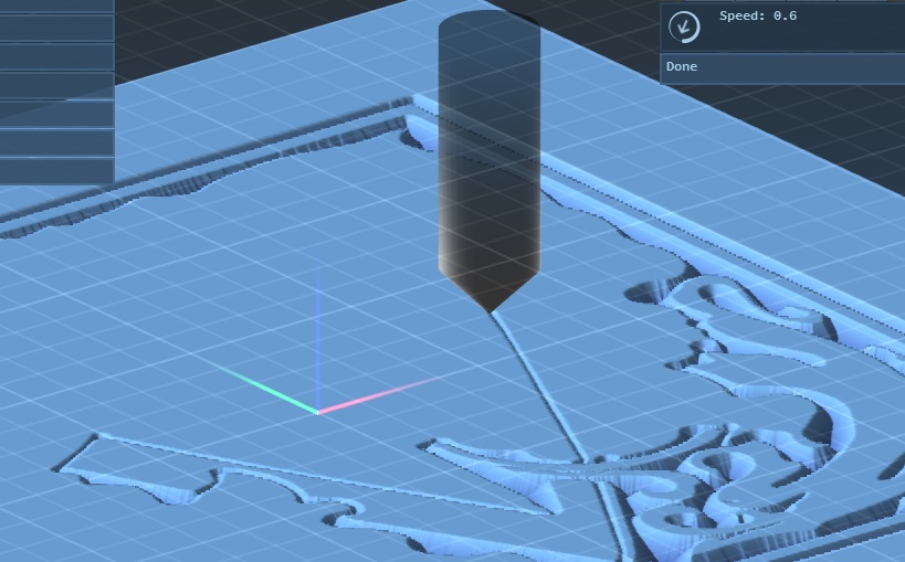
The end result is that the tool follows the simulation as it progresses through an operation. This makes it easier to see where the cutting is happening.
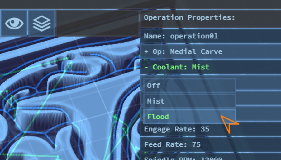
Operation Coolant
There is a new operation property that allows setting the CNC machine coolant mode that should be used for the duration of the operation:
Parallel Toolpath Bugfix
A bug was fixed in the parallel contouring toolpath generation code that produced a stray cut at the very end of the toolpath which traveled from the end of the last cut back toward the project's origin. This occurred specifically when the 'mixed' cut direction is used, and the parallel cuts are angled at greater than 270 degrees:
Stipple Advection
The stipple operation's toolpath generation has been reworked to situate stipple points much better than the old method. The old method involved 'surfing the gradient' of the image, causing stipples to slide along image brightness toward lighter/darker, depending on whether the advection parameter is positive or negative. This just ended up in a blurry and less-detailed stipple pattern, and forced the user to also rely on the Size Contrast parameter to control the size of each stipple point according to the brightness of the image at its location.
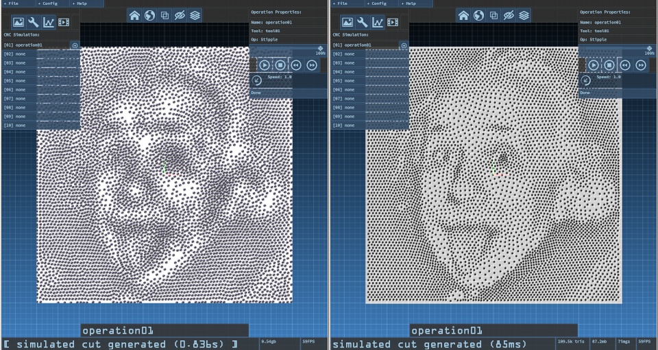
The image above shows the same PixelCNC project loaded into v1.21a and v1.23a, and the stipple output that's generated. The photograph is conveyed rather well in v1.23a's generated stipples, in spite of the stipple diameter remaining fixed. The new stipple algorithm works by allowing stipple points to enforce a distance between them and their immediate neighbors, which is modulated by the brightness of the image at their locations.
Stipples in darker areas move closer together while stipples in brighter areas spread apart. This can still result in stipples initially bunching up together near light/dark boundaries, as they bunch together right outside a white area, but given enough advection the stipples will eventually reach an equilibrium. Now users can create stipples with a fixed-diameter, via the Size Bias parameter, and keep the Size Contrast parameter at zero, relying purely on advection to convey varying levels of brightness.
Users can still create half-tone style stipples just by setting advection to zero and then relying entirely on Size Contrast to use the image brightness to directly dictating the diameter of each stipple point. Alternatively, any combination of advection and size contrast can be tuned to produce high quality stipplings.
What's Next ?
There are dozens more fixes, enhancements, etc that have been added to v1.23a but these are just the ones I thought would be the most interesting to showcase. Now it's on to building up the list of changes for the next version (v1.24a?). The headliner for the next release includes adding support for G-code post-processors.
Yes, PixelCNC will soon be able to generate G-code for virtually any CNC controller on the planet, and not a moment too soon. Admittedly, this is a feature that should've been added sooner, perhaps before the live-simulation playback stuff (which has robbed me of 6 months of my life that I'll never get back!). The simulation playback took way more time than I meant to spend on it, but I think it's safe to say that it's finally done - and you can put a fork in it.
The post-processor system will allow users to set the post-processor that G-code should be generated with via the CNC/CAM Settings dialog under the Config menu. Posts will naturally take the form of simple ASCII text files that can be edited using any old text editor, such as Notepad. Users should be able to find the G-code specification for their CNC controller/machine and create their own posts rather easily, if one is not already included with PixelCNC that is compatible with their CNC setup. PixelCNC posts will not involve any scripting or programming, but instead take the form of lists of value assigments, similar to how MecSoft's post-processors work (https://mecsoft.com/downloadposts/)
MecSoft's post-processors are a bit more involved than PixelCNC's post format will be as PixelCNC is a much simpler CAM program. Posts will simply set various output flags, such as whether or not line numbers need to be included, which G-codes/M-codes/etc to use for various CNC commands, such as linear feeds, rapids, coolant, spindle state, etc.. Also, defining prefix/postfix blocks, and general formatting will all be controlled by the configured post-processor.
There are a bunch of little things left on the todo list, and I'll be sure to get PixelCNC to where I can move a good number of them over to the list of changes, and after post processor support is released to the public it's looking like I'll finally be able to comfortably shift gears into PR mode, and really start pushing PixelCNC out there. A big part of my marketing strategy is to make demonstration/tutorial/promotional videos. Also, I'll be giving away copies of PixelCNC to relevant YouTubers and reviewers to test out and share their experiences with their viewers and readers.
Leave a comment
Log in with itch.io to leave a comment.